Drive Firmware Security - In the Wild
Drive Firmware Security - In the Wild
This page references many technical terms and concepts detailed in the Overview page, which should be read first.
Introduction
Storage drives are notable as one of the few types of computer components for which firmware-level persistence attacks have been discovered in-the-wild, alongside UEFI/BIOS (LoJax et al) and BMCs (iLOBleed), something not merely theoretical or a conference talk demo, but actually used in the real world. Despite this, there has been little public research on the topic compared to those other targets, with technical details of how the discovered attack actually worked remaining obscure and public information largely vague.
This in-the-wild attack was published by Kaspersky in 20151, although the actual firmware implants were not documented, they detailed two separate versions of the installer used to remotely implant the firmware of a targeted drive. Beyond infecting the firmware, these installers also had the ability to read and write arbitrary data to a drive's System Area (SA), as a form of covert storage. These installers were Windows dynamic libraries named nls_933w.dll, internal version number 3.0.1 with a PE timestamp of June 2010, and 4.2.0 with a timestamp of May 2013. Version 3.0.1 supports a range of hard drive vendors (Maxtor, Seagate, Western Digital, Samsung), while 4.2.0 supports additional hard drives (Hitachi, Toshiba) and also some SSDs (Micron, OCZ)2.
Of those versions detailed above, only the earlier version 3.0.1 has a sample publicly available3 (password: infected), so that version will be the subject of this analysis. The sample is a 32-bit DLL (nls_933w.dll) that also contains a kernel driver (win32m.sys) as a PE resource.
Driver
The kernel driver win32m.sys is fairly minimal, only providing low-level interfaces to send ATA commands to drives, and containing not much else. Interestingly the PE timestamp of the driver (23/8/2001 17:03:19 UTC) appears to be forged, as the rich header shows it was compiled with Visual Studio 7.0 Rainier (released February 13 2002). The use of a custom driver at all is also interesting, as Windows versions dating back to NT4 supported standard interfaces to send ATA commands from user-mode, although such capabilities were not publicly documented until the release of Server 20034. This driver is unsigned, as was standard for 32-bit Windows before Driver Signature Enforcement was introduced, and provides its functionality through the following six IOCTLs:
IOCTL 0x870021C0 - Get Version
Returns version string, 3.0.0.0.
IOCTL 0x870021C4 - Set Main Configuration
Parses received configuration data and initialises the driver; this configuration data contains the following values:
- Driver version
- CPU count
- Number of ATA controllers (8 maximum)
- The following configuration values for each ATA controller:
- Device type (IDE, AHCI, NVIDIA nForce)
- I/O type (port, memory-mapped)
- PCI vendor ID
- PCI device ID
- Command base-address
- Control base-address
- MMIO region size
IOCTL 0x870021C8 - Cleanup
Clears current configuration and uninitialises the driver.
IOCTL 0x870021CC - Get Main Configuration
Reads the current configuration data set through IOCTL set main configuration.
IOCTL 0x870021D0 - ATA Command
Executes an ATA command with the provided registers and data buffer, on a drive selected by controller number, port number, and drive number (master/slave). It supports flags to control transfer direction (read/write) and register size (LBA28/LBA48), however it does not support DMA transfer, only PIO ATA commands can be executed.
IOCTL 0x870021D4 - ATA Command Configuration
Configures various parameters used when executing ATA commands with IOCTL ATA command. This includes a timeout, retry count, and ATA controller poll interval.
Dispatcher
The library nls_933w.dll provides the main functionality and logic of this installer, containing everything important up to dispatching low-level ATA commands through a generic interface provided by the driver. It has a PE timestamp of 15/6/2010 16:23:37 UTC, which seems appropriate matching other metadata and functionality of the library, so may be genuine unlike the kernel driver.
The library has strings encrypted with a XOR-based cipher, and makes heavy use of complex C++ class hierarchies, but is otherwise unobfuscated. It exports five separate ordinals, designed for the specific malware framework this library is deployed and used through, descriptions of each of these ordinals are provided below:
- Returns a pointer to a dispatch function that handles requests to module functionality.
- Initialises callback function pointers from a structure provided as an argument, RC5-CFB decrypts a string table resource used internally by the library.
- Just returns 1.
- Initialises structure pointer passed as a parameter with the module version (3.0.1).
- Initialises structure pointer passed as a parameter with module ID (
0x80AB).
The main dispatcher function returned by ordinal 1 handles operation codes ranging from 0x51 to 0x64 inclusive:
Dispatcher pseudocode
unsigned int DispatchRequest(Request **request, size_t *request_size) {
  if (request_size != NULL) {
    if (request != NULL && *request != NULL) {
      if (ComputeChecksum(*request, *request_size) == 0) {
        switch((*request)->opcode) {
        case 0x51:
          return Handle_InstallService(request, request_size);
        case 0x52:
          return Handle_UninstallService(request, request_size);
        case 0x53:
          return Handle_GetVersion(request, request_size);
        case 0x54:
          return Handle_EnumerateDrives(request, request_size);
        case 0x55:
          return Handle_SADumpFile(request, request_size);
        case 0x56:
          return Handle_SALoadFile(request, request_size);
        case 0x57:
          return Handle_Get5a5a(request, request_size);
        case 0x58:
        case 0x59:
        case 0x5a:
        case 0x5b:
        case 0x5c:
        case 0x5d:
        case 0x5e:
        case 0x63:
          return Handle_Operations_0x58_to_0x5e_and_0x63(request, request_size);
        case 0x5f:
          return Handle_SelectDrive(request, request_size);
        case 0x60:
          return Handle_DeselectDrive(request, request_size);
        case 0x61:
          return Handle_SALoad(request, request_size);
        case 0x62:
          return Handle_SADump(request, request_size);
        case 0x64:
          return Handle_SupportedDriveTypes(request, request_size);
        default:
          return 0x302;
        }
      }
      *request_size = 0;
      return 0x306;
    }
    *request_size = 0;
  }
  return 0x303;
}
Rather than being a simple installer that just autonomously performs all operations to infect a drive, this library is instead a handler for performing singular low-level operations on a drive one at a time, with much of the actual logic done remotely on the command-and-control side. A drive is first selected with opcode 0x5F, then other opcodes are used to perform various operations on that selected drive. Each operation handled by this dispatcher is detailed in its own section.
Implant Data Storage
The library implements a fascinating set of functionality related to managing a custom structure of data stored in the drive System Area (SA), data that also seems to be used internally by a firmware implant installed in the drive. The structure of that data, and the process of how it is accessed, are detailed below.
Implant Data Storage - Structure
This structured data uses two levels of indirection. Firstly, a set of extents representing areas of CHS-addressed ranges of the SA is used to manage potentially multiple discontinuous SA areas as a single contiguous storage area. Over those extents a set of allocations is managed, representing logical areas allocated within the combined extents, each allocation being addressed by a 16-bit integer. Details of these extents and allocations are stored within a header, with that header itself being assigned allocation ID 0xFFFD.
The header begins with the following structure:
D0 AC 68 24 01 1-byte unknown 2-byte sector count 2-byte extent table offset 2-byte allocation table offset 2-byte checksum.
Where sector count represents the size of the header in sectors, extent table offset is the offset in the header at which a table of extent entries begins, and similar allocation table offset is the offset to the table of allocation entries. The checksum is a value such that a 16-bit word sum of the header equals zero.
The extent table is a series of entries terminated by the bytes FE FF FF FF, where each entry has the following format:
4-byte logical sector 4-byte CHS 4-byte sector count
Where logical sector is a sector number representing a logical position within the combined area of all extents, CHS represents a packed CHS address where the extent is located, and sector count represents the extent size as a number of sectors.
The allocation table is a series of entries terminated by the bytes 00 00, where each entry has the following format:
2-byte ID 4-byte sector 4-byte sector count
Where ID represents an integer uniquely identifying each allocation, sector is the start position within the combined extents area as a sector offset, and sector count is the allocation size as a number of sectors. Although the sector count is stored as a 32-bit value in the structure, the code constrains it as a non-zero 16-bit value, meaning allocations can be sized from 512 to 33,553,920 (512 aligned) bytes.
The following allocation IDs are used to store the described types of data:
| Allocation ID | Size | Description |
|---|---|---|
0x2 |
33 sectors | State/configuration data, starts with a 1-sector header with various flags, related to 0x101 |
0x3 |
32 sectors | Unknown, only written with 16,384 null bytes and never read |
0x100 |
1 to 65,535 sectors | Likely covert storage |
0x101 |
1 to 65,535 sectors | Likely payload of MBR substitution, related to 0x2 |
0x8000 to 0x80FF |
Unknown | Reserved range, possibly used internally by firmware implant |
0xFFFD |
>=1 sector | Data storage header |
0xFFFE |
N/A | Free space marker |
0xFFFF |
1 to ? sectors | Likely internal scratch space, allocated before then freed after certain operations |
The key allocation IDs are 0x100 and 0x101, the only allocations used to store any data larger than a few sectors in size.
Allocation 0x101 appears closely tied to 0x2, with many areas of the library allocating or accessing these together as part of a single high-level operation. Allocation 0x101 also appears closely related to some core functionality of the firmware implant, with drive-specific implementations of the load SA operation likely used for implant installation having functionality specific to this allocation ID. As such the most likely hypothesis is this allocation is used to store the payload executed on the computer through MBR substitution.
In contrast allocation 0x100 appears more related to some extra optional functionality. The only use of this allocation ID in the library is simply implementing raw read and write operations for the contained data, with no inbuilt parsing or other handling logic like other allocation IDs have. The most likely intent of this allocation ID is an area of covert storage, where external arbitrary data can be written to the drive SA for later reading.
Implant Data Storage - Access
Each drive type provides different implementations of a set of low-level primitives used to manage this data in the System Area (SA), with each implementation using Vendor Unique Commands (VUCs) and related logic specific to the drive type. These primitives are reading data from a Cylinder-Head-Sector (CHS) address, writing data to a CHS address, and reading a CHS address value from the drive.
The read and write CHS data primitives are fairly intuitive, simply reading or writing data to the drive at a specific raw CHS address location, which can be used to access the drive System Area (SA).
The read CHS address value primitive however is more unusual, this implements drive-specific reading and parsing logic to extract a 32-bit value from the drive, which represents a packed CHS address that locates the header of the structured data stored in the SA. Rather than this packed CHS value being some parameter or value related to the drive's standard firmware or functionality, this value actually seems to originate from a custom firmware implant installed in the drive. For standard drives with factory-original firmware, the drive-specific implementations of this primitive do not actually appear capable of obtaining a valid CHS address, they appear intended for use only with some modified form of firmware that supports the specific logic implemented.
An example of how the vendor-specific primitives described above are implemented for a drive type is detailed in WD ROYL - implant data storage. The library uses these primitives to implement a generic interface to manage a common format of structured data in the SA, the same for every drive type.
It first uses the drive-specific read CHS value primitive to read a 32-bit packed CHS address from the drive, an address it then reads 512 bytes of data from using the read CHS data primitive. This 512-byte data is parsed at the start of the header detailed in implant data storage - structure, validating it starts with bytes D0 AC 68 24 01 and reading the sector count value from offset +6, this sector count is then used to re-read the full data of the header and parse it.
With the header parsed, including the contained tables of extents and allocations, the CHS read and CHS write primitives are then used to access and manage the various allocations, with a new header structure also written if necessary with the CHS write primitive.
Operation 0x51 - Install Driver
Installs driver service (win32m.sys).
Operation 0x52 - Uninstall Driver
Uninstalls driver service (win32m.sys).
Operation 0x53 - Get Version
Returns string 3.4.1, likely an internal version number for something, though different from the main library version of 3.0.1.
Operation 0x54 - Enumerate Drives
Enumerates all available drives, returns various information from ATA command 0xEC IDENTIFY DEVICE.
Operation 0x55 - Dump SA to File
Dumps a range of various data from the System Area (SA) of the current drive selected with operation 0x5F to a file in a custom format, this format is based on multiple layers of encapsulated containers.
Operation 0x55 - Dump SA to File - Encrypted Container
The outermost container, referred to here as the encrypted container, starts with an unencrypted header of the following format:
4-byte checksum 4-byte checksum+1
Where the checksum is a 16-bit word sum of the unencrypted container contents, and checksum+1 is simply that checksum value incremented by 1. The 8-byte data of this header is later used as the Initialisation Vector (IV) for encryption.
This header is then followed by RC5-CFB encrypted data, where the data encrypted is the magic string 22220000 followed by the container contents. This encryption uses the following hardcoded key:
A0 1E D6 EA 83 89 A2 A0 AA 44 AA D3 EC 35 F5 F3
Operation 0x55 - Dump SA to File - Common Container
Inside the encrypted container another container is found, similar to the encrypted container this uses a single format common to all drive types, so it will be referred to here as the common container. This container has its contents prepended by a header of the following format:
21 93 2-byte drive type 01 00 2-byte checksum
Where the drive type is as detailed in operation 0x64, and the checksum is a value such that the 16-bit word sum of the entire container (including this header) equals zero.
Operation 0x55 - Dump SA to File - Specific Container
Inside the common container there is yet another format of structured data, however this is completely specific to each different drive type, and has no common format. As such, it is referred to here as the specific container. For all drive types this will generally contain a list of records representing different types of SA or other internal data for the drive. An example of how this container is implemented for a drive type is detailed in WD ROYL - dump SA to file.
Operation 0x56 - Load SA From File
Related to operation 0x55 above, this parses a file of the exact same structured format and writes it to the current drive selected with operation 0x5F.
However this is not necessarily a simple inverse of operation 0x55. For some drive types certain specific container record types produced by Dump SA are rejected by this Load SA operation and cause it to fail, it can also support additional record types Dump SA cannot produce. This means even though they work with the same format of structured data, the actual output/input of these operations is not always compatible for all drive types.
Operation 0x57 - Get 0x5A5A
Just returns integer 0x5A5A, unknown purpose.
Operations 0x58 to 0x5E and 0x63 - Implant Data Management
These operations collectively manage allocations within the implant data storage structure, each designating a type of action to perform on these allocations, detailed below:
| Operation | Description |
|---|---|
0x58 |
Read metadata |
0x59 |
Reset |
0x5A |
Set flag |
0x5B |
Clear flag |
0x5C |
Clear data |
0x5D |
Read data to file |
0x5E |
CRUD operations |
0x63 |
Read data inline |
All of these operations share common sub-operation codes which designate which allocation to perform the action on and how, some operations do not support certain sub-operations, and some sub-operations only support a certain drive type. Details of each sub-operation are listed below:
| Sub-operation | Supported operations | Supported drives | Description |
|---|---|---|---|
0x1 |
0x58, 0x59, 0x5A, 0x5B, 0x5C |
Seagate (Type 1) | Unknown purpose, special case unique to drive type, uses single-sector transfers through VUC protocol |
0x2 |
All except 0x5E |
All | Likely for implant configuration/payload, uses allocation ID 0x2 for metadata and 0x101 for data |
0x4 |
0x58, 0x5C, 0x5D, 0x5E, 0x63 |
All | Likely for covert storage of arbitrary data, uses allocation ID 0x100 |
Interestingly for operation 0x5C and sub-operation 0x2 it overwrites all allocation IDs with null bytes, not just 0x2 and 0x101, except for those in the following ranges:
0x8000to0x80FF0xFFFEto0xFFFF
Operation 0x5F - Select Drive
Selects the current drive based on serial number, required before other drive operations. The library sends various ATA commands to fingerprint and discover what type of drive it is, it creates classes of every supported drive type, then iterates through each calling a verification method on the drive until one returns a match:
Select drive pseudocode
class DriveManager {
    ...
    std::vector<DriveHandler*> handlers;

    DriveManager() {
        handlers.push_back(new MaxtorHandler());
        handlers.push_back(new Seagate1Handler());
        handlers.push_back(new WDROYLHandler());
        handlers.push_back(new SamsungHandler());
        handlers.push_back(new WD1Handler());
        handlers.push_back(new SeagateF3Handler());
    }

    Drive* CreateDrive(DriveInfo* drive_info, DriveAddress* drive_address) {
        for (DriveHandler* handler : handlers) {
            if (handler != nullptr && handler->IsSupported(drive_info, drive_address) == 0) {
                Drive* drive = handler->CreateDrive(drive_info, drive_address);
                if (drive != nullptr) {
                    return drive;
                }
            }
        }
        return new Drive(drive_info, drive_address);
    }
    ...

};
As shown in the above code, this library supports six different major types of drives, though some of those perform additional checks internally to identify minor sub-types. The checks used to identify each drive type are mostly based on the result of ATA command 0xEC IDENTIFY DEVICE, and are detailed below:
Maxtor
-
WWN starts with 5001075
OR
-
Model name starts with Maxtor but does not start with Maxtor STM, and firmware version does not contain a "." character
Samsung
-
WWN starts with 50000F
OR
-
Model name starts with SAMSUNG
Seagate (Type 1)
-
WWN starts with 5000C5 or is zero
AND
-
Model name starts with ST or Maxtor STM
AND
-
Identify device byte 275 (vendor-specific) is not P (
0x50)
Seagate F3
-
WWN starts with 5000C5
AND
-
Identify device byte 275 (vendor-specific) is P (
0x50)
WD (Type 1)
-
WWN starts with 50014EE, or model starts with WDC WD
AND
-
Identify device word 142 (vendor-specific) is 0, 1, or 2
AND
-
WD Vendor Unique Command (VUC) VSC Enable succeeds
WD ROYL
-
WWN starts with 50014EE, or model starts with WDC WD
AND
-
Identify device word 142 (vendor-specific) is 4
AND
-
WD Vendor Unique Command (VUC) VSC Enable succeeds
Operation 0x60 - Deselect Drive
Deselects the current drive if any, and resets state.
Operation 0x61 - Load SA
The same as operation 0x56, however data is loaded from memory instead of a file.
Operation 0x62 - Dump SA
Similar to operation 0x55, however the output is returned in-memory instead of written to a file. The output data also does not use the outer encrypted container, being unencrypted just in the format of the common container and contained specific container. This difference is interesting as operation 0x61 to similarly load SA data from memory does use the full encrypted format.
Operation 0x64 - Supported Drive Types
Returns a list of 16-bit IDs of each major drive type this library supports, a list of those IDs is included below:
| Drive type ID | Description |
|---|---|
0x132 |
Seagate (Type 1) |
0x133 |
Maxtor |
0x134 |
WD (Type 1) |
0x135 |
WD ROYL |
0x136 |
Samsung |
0x13A |
Seagate F3 |
Western Digital ROYL
ROYL is a generation of SATA hard drives first introduced by WD in the mid-2000s that remains in production today. In contrast to earlier generations of WD drives generally using in-house controllers, these drives use controllers designed and manufactured by Marvell. The library provides extensive functionality to target these drives.
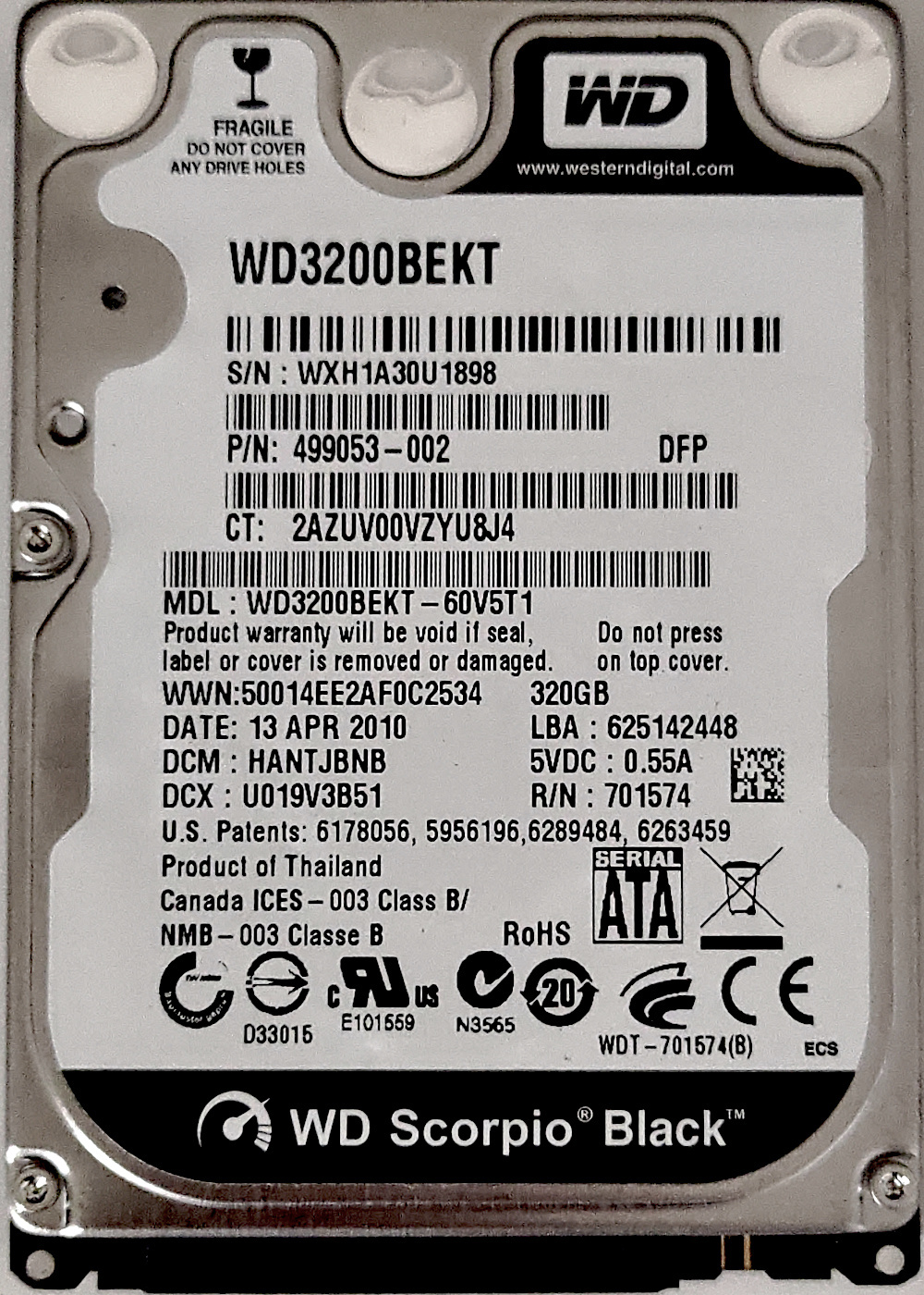
The functionality of this library was tested on a drive of this type, a 2.5-inch model WD3200BEKT-60V5T1 with a firmware version 12.01A12 and manufacture date of April 13th 2010, a few months before the compilation timestamp of the library. This drive will be referenced elsewhere in this section as the test drive, a photograph of it is included below:
Test drive photograph
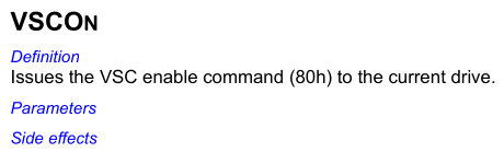
The library first unlocks Vendor Unique Commands (VUCs) for this drive with the following ATA command:
| Features | Sectors | LBA low | LBA mid | LBA high | Device | Command |
|---|---|---|---|---|---|---|
0x45 |
0xB |
0x0 |
0x44 |
0x57 |
0xA0 |
0x80 |
A 2006-dated manual for WD internal tool TREX5 refers to this command as VSC enable:
Once unlocked, commands are then sent using a vendor-specific variant of SMART Command Transport (SCT). Command parameters are written to SMART log 0xBE, a log number defined in the specification as vendor-specific, using the following ATA command:
| Features | Sectors | LBA low | LBA mid | LBA high | Device | Command |
|---|---|---|---|---|---|---|
0xD6 |
0x1 |
0xBE |
0x4F |
0xC2 |
0xA0 |
0xB0 |
That same WD TREX manual refers to this command as VSC send key:
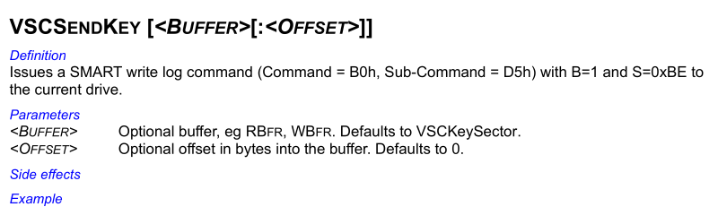
Parameter data is in the following format, where action-code designates the type of data or functionality, function-code designates a specific operation on that action-code, and function-specific parameters can be any data specific to that action and function combination:
2-byte action-code 2-byte function-code function-specific parameters
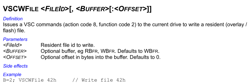
An example is action-code 8 for System Area (SA) modules and function-code 2 for writing, as detailed in the TREX manual:
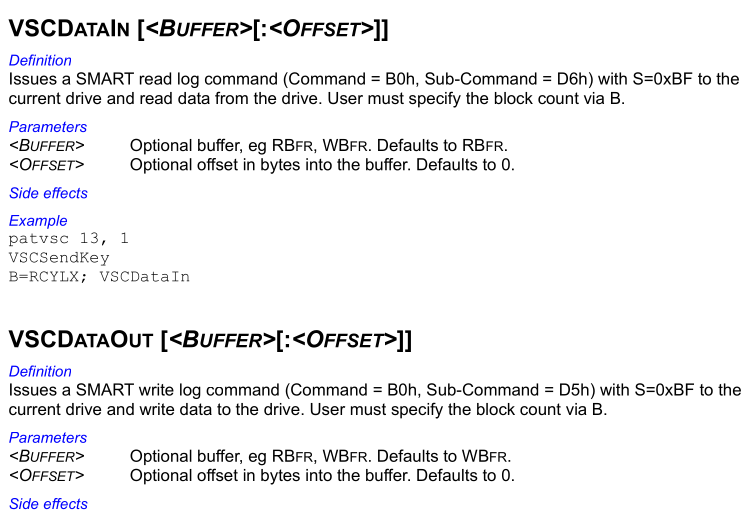
Command data is then either read or written with SMART log 0xBF, a log number also defined as vendor-specific, accessing this log also triggers the command to execute. This is done using the following ATA command:
| Features | Sectors | LBA low | LBA mid | LBA high | Device | Command |
|---|---|---|---|---|---|---|
0xD5 read / 0xD6 write |
Sectors | 0xBF |
0x4F |
0xC2 |
0xA0 |
0xB0 |
The TREX manual refers to this command as VSC data in or VSC data out:
WD ROYL - Implant Data Storage
To manage the structured data stored by the firmware implant in a reserved section of the System Area (SA), the WD ROYL class implements the primitives detailed in implant data storage - access, the same as all drive types do.
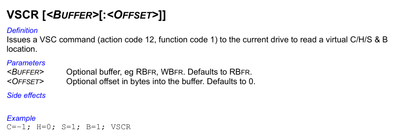
To read data from a Cylinder-Head-Sector (CHS) address it uses the vendor-specific SCT system detailed above with action-code 12 function-code 1, using the following parameter data:
0C 00 01 00 4-byte cylinder 2-byte head 2-byte sector 4-byte sector-count
This is described in the WD TREX manual as reading a virtual C/H/S & B location:
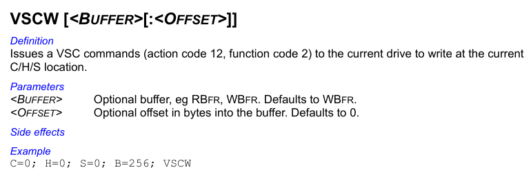
For writing to a CHS address it uses the same action code and parameter format, but with function code 2, meaning the parameter data:
0C 00 02 00 4-byte cylinder 2-byte head 2-byte sector 4-byte sector-count
The TREX manual similarly describes this command as performing a write at the current C/H/S location.
For the primitive to read the packed CHS address locating the header on disk, it first reads 512 bytes of data from the drive using unknown VUC action-code 19 with function-code 1, this action-code is not documented in the WD TREX manual or anywhere online. It uses the following parameter data:
13 00 01 00 00 00 00 00 00 02 00 00 01 00
Based on testing, this seems to be a type of memory read, taking parameters of the following format:
13 00 01 00 4-byte offset 4-byte size 2-byte unknown
The offset parameter seems to wrap around at 131,072, meaning that offset 131072 + x returns the same data as just offset x. The size parameter supports a maximum value of 122,880, and the unknown parameter seems to have no effect. The data returned starts with an ARM exception vector table followed by various firmware code and related data, some areas of data returned can be slightly different between reads at different times, indicating it likely reads from RAM of the drive controller.
For the test drive this returns the following data:
VUC action-code 19 read data
00000000: 58 f0 9f e5 58 f0 9f e5 58 f0 9f e5 58 f0 9f e5  X...X...X...X...
00000010: 58 f0 9f e5 00 00 a0 e1 70 f0 9f e5 68 f0 9f e5  X.......p...h...
00000020: 4c f0 9f e5 5c f0 9f e5 38 f0 9f e5 4c f0 9f e5  L...\...8...L...
00000030: 4c f0 9f e5 00 00 a0 e1 38 f0 9f e5 38 f0 9f e5  L.......8...8...
00000040: 2c f0 9f e5 3c f0 9f e5 18 f0 9f e5 2c f0 9f e5  ,...<.......,...
00000050: 2c f0 9f e5 00 00 a0 e1 18 f0 9f e5 18 f0 9f e5  ,...............
00000060: 53 4c e2 ff 68 d4 f2 ff 64 03 e3 ff 04 d5 f2 ff  SL..h...d.......
00000070: 44 d5 f2 ff 28 03 e3 ff 24 03 01 00 60 f4 00 00  D...(...$...`...
00000080: 0c 74 e1 ff 14 74 e1 ff 00 74 e1 ff 7c 00 01 00  .t...t...t..|...
00000090: 04 9e 00 00 0e 40 2d e9 00 10 4f e1 00 20 0f e1  .....@-...O.. ..
000000a0: 02 f0 61 e1 04 e0 8f e2 10 ff 2f e1 01 f0 61 e1  ..a......./...a.
000000b0: 0e 80 bd e8 c0 46 00 00 10 0f 6f e1 1e ff 2f e1  .....F....o.../.
000000c0: 01 c0 5e e5 0c 00 53 e1 03 30 de 37 0c 30 de 27  ..^...S..0.7.0.'
000000d0: 83 e0 8e e0 1e ff 2f e1 61 4a 01 01 50 58 89 18  ....../.aJ..PX..
000000e0: 09 89 81 29 08 d0 83 29 08 d1 80 88 d0 28 03 d0  ...)...).....(..
000000f0: d5 28 01 d0 d6 28 01 d1 01 20 70 47 00 20 70 47  .(...(... pG. pG
00000100: f8 b5 27 f6 61 fa 1f 20 27 f6 fc f8 55 4e 56 4d  ..'.a.. '...UNVM
00000110: 56 48 ae 60 00 68 56 49 57 4f 48 62 55 48 68 60  VH.`.hVIWOHbUHh`
00000120: ff 20 28 70 a8 68 69 68 00 22 08 40 81 21 00 f0  . (p.hih.".@.!..
00000130: df ff 52 49 04 1c 08 40 02 d0 ff 20 18 f0 f0 ef  ..RI...@... ....
00000140: 4f 48 20 40 07 d0 00 ab 19 78 20 1c 27 f6 4b f9  OH @.....x .'.K.
00000150: 4b 48 c0 43 04 40 48 48 60 38 20 40 20 d0 02 f0  KH.C.@HH`8 @ ...
00000160: 51 f9 48 4a 01 21 28 70 ff 28 51 60 18 d0 46 49  Q.HJ.!(p.(Q`..FI
00000170: 09 78 89 07 01 d5 19 f0 34 e8 28 78 02 f0 99 f8  .x......4.(x....
00000180: 28 78 ff f7 a9 ff 00 28 06 d0 38 1c 3c 40 c9 d0  (x.....(..8.<@..
00000190: 01 21 01 f0 2d f8 c5 e7 3c 48 01 21 01 f0 28 f8  .!..-...<H.!..(.
000001a0: 35 48 80 30 20 40 0d d0 30 48 ae 60 00 68 30 49  5H.0 @..0H.`.h0I
000001b0: 48 62 28 78 ff 28 03 d1 35 48 30 f6 4e e8 01 e0  Hb(x.(..5H0.N...
000001c0: 02 f0 77 f8 33 48 04 40 20 1c 38 40 aa d0 02 20  ..w.3H.@ .8@...
000001d0: 69 46 02 f0 87 fc 30 48 80 7d 06 28 24 d0 bc 43  iF....0H.}.($..C
000001e0: 2b d1 a8 68 b0 42 28 d1 2c 48 2d 49 80 78 89 7e  +..h.B(.,H-I.x.~
000001f0: 08 43 c0 07 21 d1 28 f6 82 f9 00 28 1d d0 29 48  .C..!.(....(..)H
Full data returned from this command with offset 0 and size 122,880 is available at vuc-action-19.bin.
It then parses that read data as a 32-bit little-endian ARM exception vector table, extracting the packed CHS address from an offset varying based on checks for specific instructions at two of the vectors. These checks are for the Reserved vector at offset +20, an unused vector normally containing a No-Operation (NOP) instruction variant, and the Fast Interrupt Request (FIQ) vector at offset +28, a vector for highest priority hardware interrupts normally used for critical low-latency tasks.
The checks and resulting CHS address offset it uses are the following:
| Reserved vector | FIQ vector | CHS address offset |
|---|---|---|
00 00 A0 E1 (mov r0,r0) |
18 F0 9F E5 (ldr pc,[pc,#0x18]) |
0x34 |
01 10 A0 E1 (mov r1,r1) |
N/A | 0x3C |
02 20 A0 E1 (mov r2,r2) |
N/A | 0xB4 |
03 30 A0 E1 (mov r3,r3) |
N/A | 0x5C |
For the test drive, none of these sets of checks actually match. The first set is close, with the reserved vector check matching, however the FIQ vector instruction is 68 F0 9F E5 (ldr pc,[pc,#0x68]) which fails that check.
The incompatibility of the test drive with these checks is due to their actual purpose, a CHS address packed in a custom 32-bit format unique to this tool is never going to just be found next to the exception vector table in standard firmware. Rather than this CHS address originating from some standard drive functionality of factory firmware, it is actually from a custom firmware implant installed in the drive by this tool, basically a way for the firmware implant to tell the host computer this is where my data header is.
The exception vector table checks are verifying which of several possible firmware modifications the drive has, to identify where the CHS address should be located nearby. For the first possible option at offset 0x34 for example, the test drive has ARM NOP instruction 00 00 A0 E1 (mov r0,r0) at this position, seemingly for another unused exception vector. A packed CHS address value in an unused exception vector makes no sense for standard drive firmware; however, it makes perfect sense for a custom firmware implant, for which an unused vector is a convenient area of free space.
Kaspersky identified this functionality in their report on this malware; however, they seemed to misinterpret it as part of the firmware flashing process, possibly interpreting it as finding NOP instructions to patch with hooks for firmware modifications2:
The main function to reflash the HDD firmware receives an external payload, which can be compressed by LZMA. ... For WD drives, there is a sub-routine searching for ARM NOP opcodes in read data, and then used further in following writes.
In fact the purpose of this functionality is something perhaps even more interesting. When performed, the firmware of the drive is already infected with a custom implant, with the reads, checks, and CHS address extraction being a form of communication channel with that implant.
WD ROYL - Operation 0x55 - Dump SA to File
For dumping the System Area (SA) (operation 0x55), it first reads from the drive flash with Vendor Unique Command (VUC) action-code 36 and function-code 1, with the following parameter data:
24 00 01 00 4-byte offset 4-byte size 01
Although not documented in the TREX manual, this action-code is detailed elsewhere on the internet6. It iterates reading the flash in 65,536-byte chunks, incrementing the offset by the chunk size with each read, up to a maximum total size of 262,144 bytes (4 chunks). After the first read, if it detects that any subsequent chunk has the same data as the first chunk, it exits the loop early as a wraparound protection.
It then attempts to read a list of 29 different System Area (SA) modules from the drive. It first reads and parses module 1, the module directory, which details which modules are available, if a module is not in this directory it is skipped. The process used to read these modules is more complex than the standard VSC send key then VSC data in/out flow, with an extra step in-between.
Firstly, the VSC send key VUC is executed for action-code 8 function-code 1 using the following parameter data:
08 00 01 00 2-byte module ID
Then the current LBA mid and LBA high ATA registers are read from the drive. These register values form the low and high bytes respectively of a sector count, representing the size of the SA module attempting to be read.
That read sector count is then used with the VSC data out VUC to read the data of the SA module. The following is a list of all 29 SA modules this operation can read from the drive:
Read SA modules
| Module ID | Description |
|---|---|
0x1 |
Modules directory |
0x2 |
Drive configuration |
0x11 |
Firmware - ATA overlay |
0x12 |
Firmware - CFG overlay |
0x13 |
Firmware - LBA overlay 1 |
0x14 |
Firmware - Unknown overlay 1 |
0x15 |
Firmware - Techno overlay 1 |
0x17 |
Firmware - LLF overlay |
0x19 |
Firmware - Unknown 1 |
0x1B |
Firmware - Transient overlay |
0x1C |
Firmware - Techno overlay 2 |
0x1E |
Firmware - Techno overlay 3 |
0x1F |
Firmware - Unknown 2 |
0x4C |
Firmware - LBA overlay 2 |
0x61 |
Firmware - DRVPROT overlay |
0x80 |
Firmware - Unknown 3 |
0x21 |
SMART log current 1 |
0x22 |
SMART log current 2 |
0x23 |
SMART log clear |
0x24 |
SMART log main |
0x2A |
Firmware - Unknown 4 |
0x2F |
Firmware - Unknown overlay 2 |
0x50 |
Acoustic profile - main |
0x51 |
Acoustic profile - alt 1 |
0x52 |
Acoustic profile - alt 2 |
0x53 |
Acoustic profile - alt 3 |
0x6E |
Firmware - Unknown 5 |
0x108 |
Firmware - IBI overlay |
0x109 |
ROM image |
Many of these modules and their purposes are further documented in a manual for data recovery tool PC30007, and other lists available online8.
For the test drive the skipped SA modules were 0x11, 0x13, 0x4C, 0x80, and 0x109. All other SA modules in the list were read successfully. The resulting data read from the test drive by this Dump SA operation, including the flash image and SA modules, is available at dumpsa.zip.
The flash image and SA modules are then packed into the structured format detailed in operation 0x55, with a custom specific container for this drive type. This specific container starts with a header of the following structure:
22 69 01 00 2-byte checksum 4-byte size 2-byte record count
Where the checksum is a value such that a 16-bit word sum of the container equals zero, the size is the size in bytes of the container, and record count is the number of records that follow the header.
Following the header is a series of records of the following structure:
2-byte record type 2-byte checksum 4-byte size contents
Where the checksum, similarly to the header, is a value such that a 16-bit word sum equals zero, size is the size in bytes of the record, contents is simply the data of the record's contents, and record type is one of the following type values:
| Record type | Description |
|---|---|
| 1 | SA module |
| 4 | Flash image |
WD ROYL - Operation 0x56 - Load SA from File
For loading data to the System Area (SA) (operation 0x56), it decrypts and parses an input file of the same format detailed in operation 0x55, however there are differences in the types of records it supports. If the file contains a record type 4 (flash image) the entire file is rejected and the load fails, this means the output produced by the SA dump operation is not actually compatible with this SA load operation, even though they use the same structure. This SA load operation is likely the functionality used to install a firmware implant in a drive.
This SA load operation also supports additional record types the SA dump operation does not produce, all supported record types are listed below:
| Record type | Description |
|---|---|
| 1 | SA module |
| 2 | Implant data allocation ID 0x2 |
| 3 | Implant data allocation ID 0x101 |
| 5 | Implant data header flag |
| 6 | Remove SA module |
WD ROYL - Load SA - Record Type 1
For type 1 records it parses each as an SA module ID and data, writing each to the drive with VUC action-code 8 function-codes 2, with the following parameter data:
08 00 02 00 2-byte module ID
This is likely how a firmware implant is remotely installed, as WD ROYL drives store many sections of firmware as SA modules.
WD ROYL - Load SA - Record Type 2
Used for the implant data storage in the drive System Area (SA), this record is written to allocation ID 0x2.
WD ROYL - Load SA - Record Type 3
The same as record type 2, but writes to allocation ID 0x101.
WD ROYL - Load SA - Record Type 5
Related to implant data storage similar to record types 2 and 3, however this record has data of only a single byte, which is used to set a flag in the header. It reads allocation ID 0xFFFD (header of the implant data), copies the single byte of the record data to offset +5 in the header, then writes the modified header back.
WD ROYL - Load SA - Record Type 6
For type 6 records it uses the data as a 16-bit module ID. It then reads and parses module ID 1, the module directory. If an entry in the directory matches that target module ID, it is removed and subsequent entries are shifted backwards. The modified module directory is then written back to the drive, effectively removing or unlinking the given module ID. Interestingly it does not actually wipe the data of the module on disk, or do anything beyond removing the associated entry from the module directory.
Conclusion
Overall this library appears to be very well designed and engineered, with a large amount of effort clearly expended in building it. The functionality appears to have been implemented favouring the lowest-level operations possible, such as direct CHS-addressed disk access, even where simpler higher-level operations could accomplish the same thing. There seems to be a design philosophy of implementing low-level primitives specific to each drive type, on which generic functionality compatible with every drive type is built. It uses a large amount of very esoteric vendor-specific functionality for each drive type that likely could not have been obtained purely through reverse engineering, and probably involved at least some internal documentation or resources from drive vendors. Despite dating as far back as 2010 this version already seems fairly mature, with a large amount of functionality for several different types of drives, it is likely this tool had been in development for at least several years prior to this version.
-
https://securelist.com/inside-the-equationdrug-espionage-platform/69203/ ↩
-
https://media.kasperskycontenthub.com/wp-content/uploads/sites/43/2018/03/08064459/Equation_group_questions_and_answers.pdf ↩
-
https://www.virustotal.com/gui/file/83d14ce2dcfc852791d20cd78066ba5a2b39eb503e12e33f2ef0b1a46c68de73 ↩
-
https://www.smartmontools.org/wiki/FAQ#OnWindowssmartctlprintsthemessage:...LogReadfailed:Functionnotimplemented ↩
-
https://trulycrisp.github.io/drivefirmware/inthewild/trex_manual.pdf ↩
-
https://web.archive.org/web/20230217034243/http://yura.puslapiai.lt/files/wd/mhdd/ ↩
-
https://trulycrisp.github.io/drivefirmware/inthewild/pc3000_wd_marvell_manual.pdf ↩